
The key objective of this blog is to focus on lean product design methods, which enables creation of lightweight products meeting all their functional requirements at a reduced cost & time. The two main technologies that will be reviewed in this blog are Generative design and Topology Optimization. The main attributes covered under these technologies are definitions, methodology, software’s, advantages, prerequisites, precautions, comparison, and Improvians take on them.
Generative Design
DEFINITION
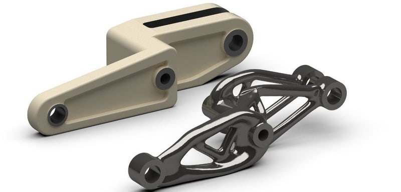
Generative design uses an iterative approach to generate multiple CAD ready solutions based on manufacturing constraints and product performance requirements such as dimensions, mass, material,and strength. Generative design along with additive manufacturing has generated a lot of new avenues to achieve innovate product design which is feasible to manufacture.
Methodology
1. Interface Geometry
This step involves defining all the mating or connecting parts. This works as a base for your generative design study and helps it understand how your generative design will be connected to the rest of the design.
2. Geometry to Preserve and Obstacles
In this step, those design features are defined which should not change during the design process. These may include standard geometries such as holes for fastening, cut-outs, projections for locating, etc. Next, the user also needs to define external geometries present in the assembly which will prevent the software to add material in those regions (obstacles). This step depends on a particular application and its optional.
3. Loads and Constraints
As generative design is a simulation process, it needs loads and constraints on the geometry per the design specification similar to how it is done in finite element analysis (FEA).
4. Design Criteria
In this step, design criteria are generally defined using the below attributes:
- Stress: You can specify the maximum permissible stress allowed to be induced in your generated design.
- Stiffness: It is used to control deflection of part. Higher the stiffness, lower the deflection and vice versa.
- Factor of Safety (FOS): This ensures that all the generated designs have a certain minimum FOS. The software may generate designs having higher FOS than specified.
5. Manufacturing Method
Manufacturing considerations can be specified during this step but the methods are limited to casting, injection molding, 3 axis, 5 axis, and 3D printing. It can be skipped but then generated design might not be possible to manufacture at all or only by 3D printing.
6. Materials
User can select materials for which the design needs to be generated. Each simulation will be performed with a single material at a time. However, with recent development, some software platform e.g. CogniCAD are even starting to develop multi-material designs which allows use of different materials in high and low stresses regions in a single part.
Once all the steps are completed, the software generates 100s to 1000s of possible designs that satisfy all the constraints. It also gives a plot that shows performance of each design on different parameters such as weight, stress, FOS, deflection, etc. The designer can select any of the relevant design based on his preference.
Some of the Leading Companies offering Generative Design technology:
- Autodesk -> Fusion 360 (Cloud only)
- Siemens -> NX & Solid Edge
- PTC -> Creo
- Dassault Systèmes -> CATIA-Generative Shape Design
- ParaMatters -> CogniCAD (Cloud Only)
- Desktop Metals -> Live Parts (Cloud Only)
- MSC -> Apex
Advantages of Generative Design
- It generates lightweight designs.
- It gives you 1000s of options to choose which wouldn’t have been possible otherwise.
- The lead-time of the design cycle reduces drastically because designs are generated quickly and the designer only has to select and validate the design.
- It eliminates the bias behavior designer may have due to his experience and knowledge in generating a new design.
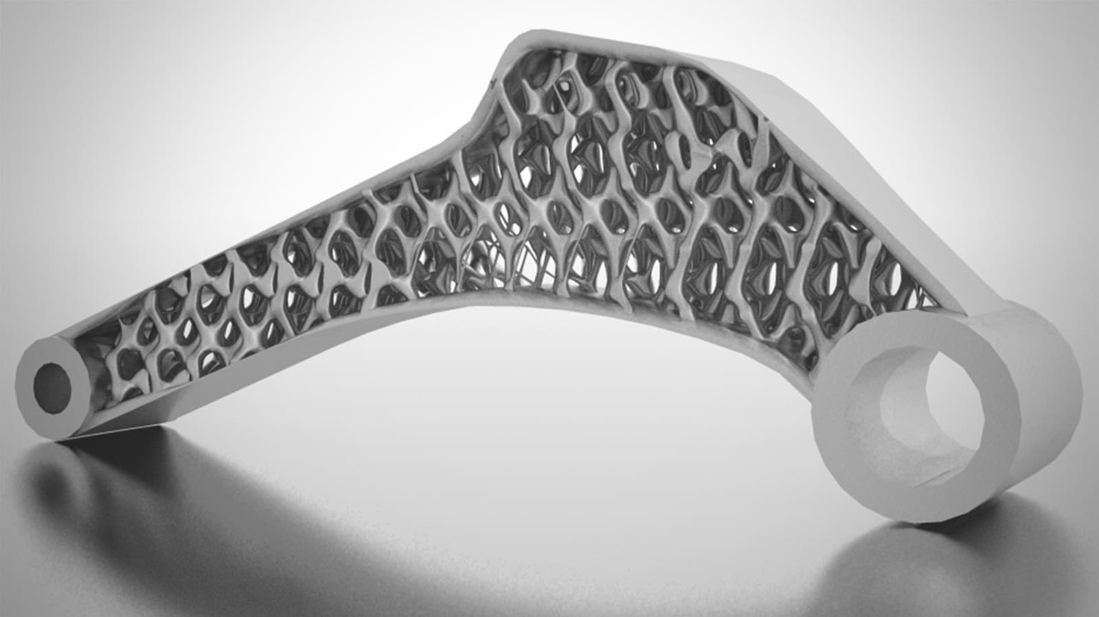
- With additive manufacturing, lattice structures can be assigned to inside of the part, which allows the flexibility to change the stiffness in the different areas of the parts.
Topology Optimization
DEFINITION
Topology optimization is a mathematical method that optimizes material layout within a given design space, for a given set of loads, boundary conditions and constraints to minimize the material while meeting the functional requirements.
Methodology
1. Initial Design:
Topology optimization process starts after the designer has completed an initial design that fulfills all the functional requirements. This design serves as the base for the optimization process.
2. Loads and Constraints:
Topology Optimization also requires boundary conditions and constraints. The design space is existing design body which is being optimized. User has to define the design space where the optimization algorithm is permitted to remove material. Next, the loading conditions and fixed points need to be specified according to the part functionality. After that, material has to be mentioned for Topology Optimization. This process can be repeated for different materials, loads, and constraints.
3. Meshing:
In this step, the design body is converted to mesh. User defines different meshing parameters such as type of element, quality of mesh (coarse or fine), size of elements, etc. The finer meshing generates more accurate results however it takes longer to complete the simulation.
4. Optimization Parameters:
Next, the optimization parameters for the part needs to be defined. Generally, you can choose between following parameters.
- Stress/Factor of Safety (FOS): You can specify maximum stress or minimum factor of safety based on your design specification.
- Target Weight: If you already have a set target weight for your product, you can specify in this step. The optimization process will stop once the target weight is achieved. It is not an ideal option in situations where you want to maximize reduction in weight. If target weight specified for Topology Optimization is too low, study will most likely fail.
- Number of Runs & Convergence: You can set the number of runs if you want the optimization process to complete in a stipulated time. The trade-off here is results may not be most optimal. Another option is to select convergence criteria, wherein the optimization process will complete if the change in weight between two sequential simulation iteration is less than convergence criteria. A general method can be to define maximum allowable stress or minimum factor of safety along with convergence criteria. However, the time taken for these criteria is unpredictable and may take too long to complete. If that happens, alternate approach could be user can set target weight with number of runs and convergence criteria to complete the process quicker.
5. Manufacturing Method
With recent developments in software, topology optimization can be performed with manufacturing methods as constraints. The general manufacturing methods available are casting, injection molding, 3 axis, 5 axis, and 3D printing.
6. Final Output:
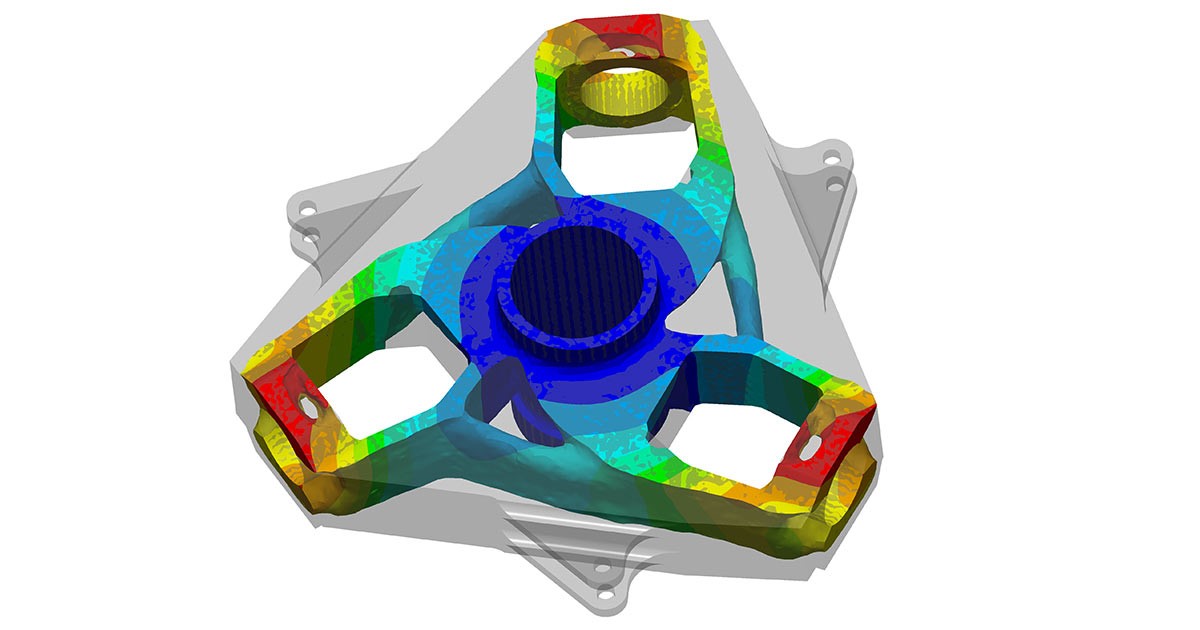
After completing steps1 to 5, you can run the study to get the topology optimized part. It is advisable to run a FEA simulation on the optimized part to ensure induced stress and deflections are within specification limits.
Computer-Aided Design (CAD) Softwares vs Computer-Aided Engineering (CAE) Softwares for Topology Optimization:
Below are some of the software that offer Topology Optimization:
CAE software is generally used for more specialized and critical applications because it allows a lot more control over meshing, loads, material properties, etc. The trade-off is increased time in training, high software cost and difficulty to make changes in initial design in the CAE software.
Advantages of Topology Optimization :
- It reduces weight while limiting stress or FOS.
- It improves stress distribution.
Prerequisites & Precautions for Topology Optimization and Generative Design :
- It requires a trained designer to put correct boundary conditions and ensure all possible failure modes are part of the input conditions.
- For Topology Optimization, the computational power required is high taking from several hours to days depending upon geometry size, number of elements and number of runs, if done on the local system. For Generative Design, it is even higher and mostly done through cloud computing.
- The output design in some cases requires post-processing to meet the manufacturing feasibilities & reduce machining cost.
- Human element is still missing in both these technologies. So certain design modifications may be required to make the part aesthetically pleasing.
TOPOLOGY OPTIMIZATION VS GENERATIVE DESIGN
Although Topology Optimization and Generative Design have been used synonymously & interchangeably, they are quite different. Even with same input condition, they can generate very different results. Below are the key differences between generative design and topology optimization:
Methods of modifying output for Topology Optimization & Generative Design:
As we have already discussed that both Topology Optimization and Generative Design outputs are organic shapes that can be difficult to manufacture especially if manufacturing constraints are not given. In that case, there are some software available to convert these organic shapes into the standard shapes and also to make the organic shape single body into conventional feature-based models. These methods are used for reverse engineering which involves scanned & faceted data. There are commercial softwares available for converting faceted data to standard feature-based CAD models. Below is the list of these softwares:
- Geomagic Design X
- Space Claim
- Xtract3D (Plug-in for SolidWorks)
- Mesh2Surface (Plug-in for Rhino 3D)
Improvians Take
Topology Optimization and Generative Design are very powerful tools to create optimized designs. Topology Optimization which has been around for generations is mostly used after your initial design is finalized to further reduce its mass. Generative design, which is lot newer, is used in the initial design phase to autonomously generate multiple designs based on input parameters. These designs can be further filtered down by the designer based on different criteria and preferences. In both the technology, the accuracy of the output largely depends on the input boundary conditions, so it is good to have an experienced design engineering team that understands product & assembly well. Both these tools, if used correctly can help you significantly reduce product optimization lead time. Both of them may require post-processing such as filling some holes and cavities which increases machining cost but doesn’t contribute much to reducing weight, giving fillets, improving aesthetics, etc. The output of Topology Optimization & Generative Design is a single body having organic shape without any feature-based modeling. Due to this, it requires some conversions to make any modification to the CAD systems. An FEA simulation on the final product should always be done to make sure it does not exceed in induced stress & deflections. Certain modifications may be required in the final part to make them aesthetically pleasing and feasible to manufacture.
- https://caeai.com/blog/what-topology-optimization-and-why-use-it
- https://www.ansys.com/products/structures/topology-optimization
- https://solidthinking.com/product/inspire/
- https://www.ptc.com/en/product-lifecycle-report/myth-dispelled-topology-optimization-is-not-true-generative-design
- https://www.ptc.com/en/products/cad/generative-design
- https://www.autodesk.com/solutions/generative-design
- https://www.plm.automation.siemens.com/global/en/our-story/glossary/generative-design/27063
- Topology Optimization- Theory, Method andApplications, M. P. Bendsoe, O. Sigmund, Springer
- http://help.solidworks.com/2019/english/SolidWorks/cworks/c_generative_design_study.htm
- https://www.factmr.com/report/3437/generative-design-software-market
- https://www.abiresearch.com/press/autodesk-takes-top-spot-abi-researchs-generative-design-competitive-assessment/
- https://support.ptc.com/help/creo/creo_pma/korean/index.html#page/simulate%2Ftopology_optimization%2FTo_Set_Up_an_Optimization_Study.html%23wwconnect_header
- https://www.researchgate.net/post/Which_algorithm_is_used_by_commercial_FEA_solvers_for_Topology_Optimization
- https://www.engineersrule.com/performing-topology-optimization-step-step-guide/
- https://www.industryweek.com/technology-and-iiot/what-generative-design-and-why-its-future-manufacturing
Our Blogs